Connect to Second Floorplan
After the Model Link Matrix has been created, the next step is to connect to the other floor level.
-
Select
 ( Design File
Setup).
Opens the
Drawing Setup dialog.
Click on the
Building Structure tab.
( Design File
Setup).
Opens the
Drawing Setup dialog.
Click on the
Building Structure tab.
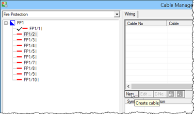
- In Cable Manager, select Circuit FP1/2, and in the Wiring section, click New. The Cable Properties dialog opens.
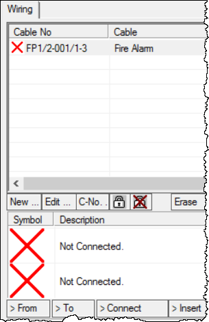
- Select Cable Type as shown, and click OK to accept settings. The selected cable type appears in the Wiring list. The red "X" are placeholders and indicate that no symbols/devices have been connected in this circuit.
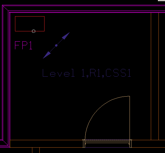
- In the Cable Manager click > Connect in the Symbols listview panel. The focus shifts in drawing view.
- Right-click mouse to reset the connection. The Cable Manager reappears. Connection between the distribution panel and the Model Link symbol is created for routing the cable to the upper floor level.
-
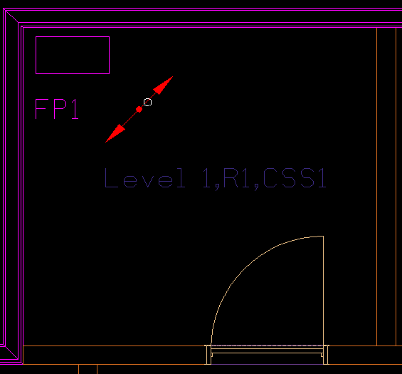
Next connect the Model Link symbol itself to the upper level.
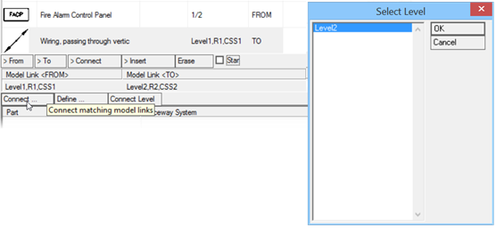
Click Model Link symbol in Cable Manager and then click
> Connect under the
Model Link <FROM> section.
In the Select Level dialog, select
Level 2 and click
OK.
The Model Link section now contains the entry Level 2,R2,CSS2.